I recently spent too much time learning about the technologies that undergird my home network.
It came about because we recently built a study in the back garden for me to use when I’m working from home. One question that remained open throughout the build was what the network setup would be. I had four critical devices: my laptop, my phone and a pair of Sonos speakers.
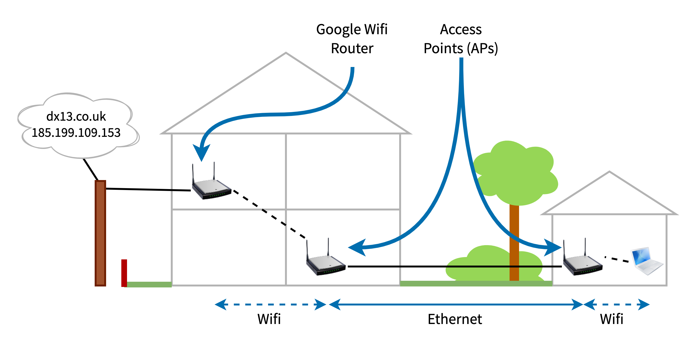
The basic connection to the outdoor study is an ethernet cable running from the house. Due to the location of my router, however, that cable is hooked into my home network via the LAN port on a Google Wifi mesh access point. I wanted to have a further wifi access point in the study, connected to the ethernet cable, for my laptop, phone and speakers. I didn’t really have much confidence, however, in using a two wifi network hop between my router (and, hence, ISP) and my laptop. It just felt weird. Too many network gizmos to work.
Buuuuut, I really, really, really wanted it to work. What better excuse to deep dive on layer two networks to figure out how wild this network really is?! So I put on my sleuthing hat and decided to figure out whether this unholy pile of network was going to work, from the network frames upwards 🕵️
What follows is the picture I put together for myself. While I’ve tried to make it accurate, there’s a bunch of (somewhat educated!) guesswork going on where I tried to apply theory to my actual devices and network.
The ideal network
The network being created would look like this:
What I needed to understand was what the network needed in order to route packets successfully in two main scenarios:
- From the laptop/phone/speakers to the outside world, so I could do my work.
- From the laptop to the speakers, to tell the speakers what to play.
These are two different problems. For the first, my laptop needs to be able to talk to my router, which is connected to my fibre broadband connection. For the second, I needed a couple of things to work: (a) the networking magic that allows the speakers to be discovered; (b) getting data to the speakers; either via AirPlay or Spotify Connect.
At this point my memory of layer two was pretty ropey. I understood that IP packets are layer three within the standard seven layer model. I knew that layer two is where data is actually routed at a LAN level and that it operates with a different data format that wraps the IP packets. And I knew that MAC addresses existed. I recalled dimly that switches were smarter than hubs. But I couldn’t remember how any of it fitted together, and I didn’t know how wifi fitted into the picture at all.
I needed to learn just enough to work out whether data could be routed correctly by all the devices. Networking is a black hole of technologies and protocols, but I hoped that a home network could avoid many of them. I figured I should start with ethernet, understanding the data format on the wire and then the routing. Then I hoped that I could bolt wifi on top of that, given it integrates into ethernet networks quite readily. I was a bit wary about Google Wifi’s mesh network, but fortunately that turned out to be standards based.
If I understood these things, I figured that I might stand a chance in hell of getting things working – and be confident it wouldn’t stop working the next day.
Network layers
First, I wanted to recap for myself what the network looks like at the level of the network devices. For my purposes, I needed to know about how data is routed around a LAN. I didn’t much care about the internet (IP). In the usual model, there are seven layers.
The first layer describes how to send a sequence of bits using changes to a physical medium – electricity in a wire, light in fibre optic cable or electromagnetic waves in the case of wifi. The second layer is the one we care about.
At the second layer we find the concept of network devices having addresses (MAC addresses) and the frame, a way of packaging up data and a destination into a particular, recognisable sequence of bits to send over layer one. The destination is a particular network interface on a particular machine on a network. This is the layer to care about if one is wondering whether a home LAN will work in a given configuration. As I was.
Layer three is where IP and the internet comes in. We can ignore the internet – we’re only dealing with routing in my home LAN – but will need to talk a bit about how the private IP addresses on the LAN are resolved into the MAC addresses used within the network.
Can my network do the routing?
My home LAN, like most networks, consists of a bunch of network devices that connect a bunch of computing devices together. Mostly wifi access points, but also switches. What we’re looking for is that these layer two network devices are able to deliver frames to the right computing devices on my network. Broadly speaking, then, the network devices – the access points and ethernet switches – need to be able to build up some sort of reliable and correct “map” of the network, with devices addressed using their MAC address, so each network device knows how to forward a received frame onward towards its ultimate destination.
So to understand what would happen with the network setup above, I needed to understand whether the wifi access points and switches would be able to build up the “maps” they needed to get data to the right places. I’d worked out by this point that my “not working” worry was, at its core, that somehow two wifi hops would leave devices without enough data to make their maps, leading to a broken network.
So I started searching the internet and reading a whole bunch of pages and online books. In real life, I ended up reading about all these things in quite a mixed up way, as I’d find different resources on the same thing that described things in a different way, which often helped fill gaps in my knowledge. I also often had to come back to old topics as I learned a new technology and needed to slot that into what I’d already learned.
After I’d cached enough data in my head, I found working through things in this order helped me get the understanding I wanted:
- Packet encapsulation.
- MAC addresses.
- Ethernet frames.
- Routing in ethernet – how switches do their thing.
- Wifi frames and access point to client connections.
- WDS (wireless distribution system) bridging.
- Wireless mesh networks.
- And then putting these pieces together to understand my network.
Let’s go 🧑💻!
Packet encapsulation
The network is layered. We care about layer two, and I found it useful to quickly check my recollection how application data ends up in a layer two frame.
An application normally starts by asking the kernel to open a TCP/IP connection to a host on the internet. The application then streams data into that connection. The kernel first breaks up the data into TCP packets (layer 4). These packets are put into IP packets (layer 3). The IP packets are then put into data link (ethernet/wifi) frames either by the kernel or the network card itself (layer 2) before being sent onto the network (layer 1, the wire or electromagnetic wave).
All “putting inside” means is that each layer adds its own metadata in the form of a header:
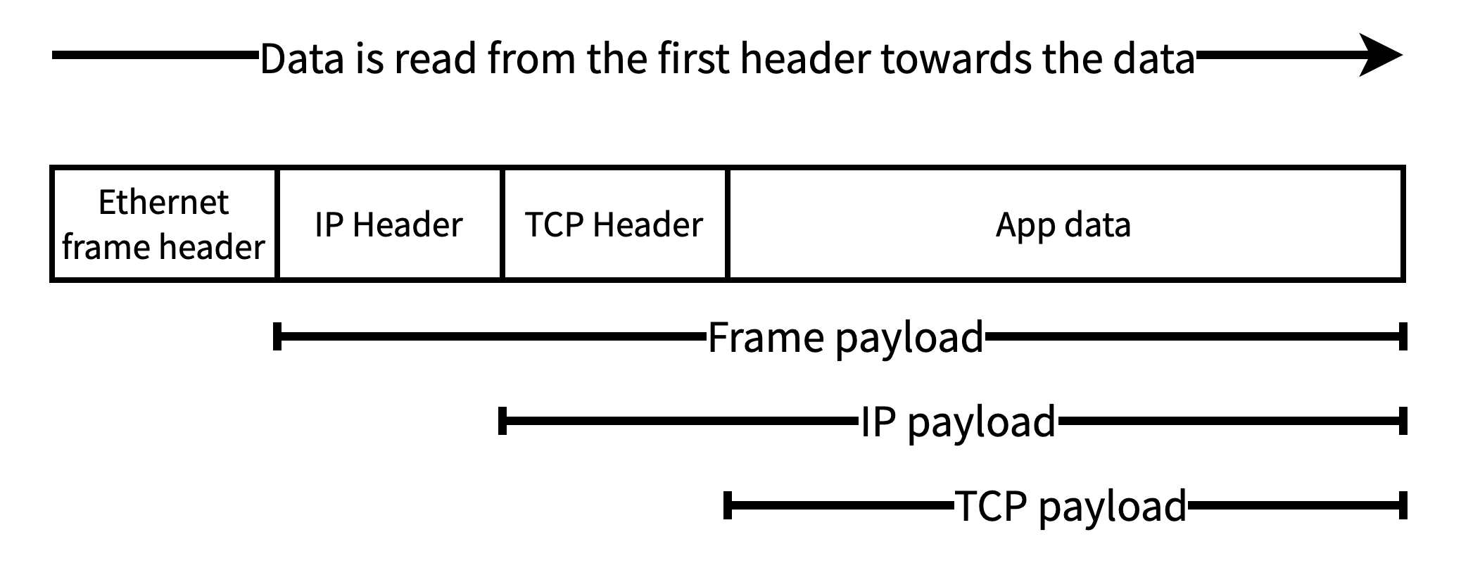
From now on, however, we’re dealing with how the layer two frame gets from the sending network interface to the receiving network interface. This is all about the frame headers; the frame payload is transparent to the layer two devices.
MAC addresses
First we have to get familiar with MAC addresses. At layer two, devices are addressed by their MAC address. A laptop may have multiple network interfaces (eg, ethernet and wifi). Each of these interfaces will have its own MAC address. The layer two network doesn’t really care that these are attached to the same laptop, they are two independently routable entities within the network. Each network interface device must have a unique MAC address within the network, otherwise the network won’t route frames reliably.
We hardly ever see MAC addresses. Our devices use ARP to translate IP addresses into MAC addresses. This uses a broadcast frame to ask all devices on a network if they are assigned a particular IP address. Typically a machine on a home network has just one IP address. A machine receiving an ARP packet requesting the MAC address for its IP address returns the MAC address of one of its network interfaces. Machines remember responses in an ARP cache/table. On macOS this can be viewed with the arp tool:
> arp -a
? (192.168.86.1) at 70:3a:cb:8d:5a:e9 on en0 ifscope [ethernet]
... other similar lines ...
This shows that on my network 192.168.86.1 has the MAC address 70:3a:cb:8d:5a:e9.
The ARP table only contains entries for IP addresses that are assigned to machines on the same network (ie, home LAN). This is because they are the only ones that will receive the broadcast frame on the network and respond. This makes sense, because those machines are the only ones that can be communicated with over layer two (ie, on the LAN), and so the only ones we need the MAC addresses for.
Communication with external IP addresses is managed using a router, using techniques like NAT to allow communication from machines in the global IP space to machines within the private IP space of a home network. From our current perspective, however, we can assume all machines on the network use ARP to find out the MAC address of the machine they need to talk to.
Frames
Frames are the layer two logical packages of data that are sent over ethernet or wifi networks between devices. The section on encapsulation showed that a frame contains a header and a data payload. As part of its header, every frame has a source and destination MAC address. These can be the MAC address of any machine on the network.
Ethernet frames
A network card sits on its ethernet cable and watches the activity on the cable (voltage changes, light in optical fibre, etc.). As it does so, it decodes the activity into bits (layer one). An incoming ethernet frame is signalled by a 56-bit preamble of alternating 1s and 0s, followed by a 1 octet delimiter 10101011. If the device sees this pattern, then it processes the bits that come afterwards as an ethernet frame (taking us up to layer two).
Once decoded, the ethernet frame consists of several fields:
- The header:
- Destination MAC address
- Source MAC address
- An optional VLAN tag
- EtherType or payload length field. The EtherType is the most common use of this field in home networks per wikipedia; it’s used to define the higher level protocol (eg, IP) encapsulated within the frame data.
- The payload data being sent, up to 1,500 octets (bytes). Often this is an encapsulated IP packet.
- A trailing checksum, allowing receivers to spot errors in the frame
While relatively simple in format, ethernet frames have a storied history. The wikipedia page has a lot more detail.
For our purposes, though, the source and destination MAC addresses are the important information. It’s clear why we need the destination address: we need to know where the data is going! The reason for also having the source address more subtle. One important role it plays is allowing network hardware, like switches, to build up internal MAC address tables of “next hops”.
Switches
There may be many pieces of hardware between a frame’s source and its destination. Each device that the frame traverses on its way is called a “hop”. The job of each piece of networking hardware is to use the destination address to find the next hop for each frame it receives. Eventually, a frame will traverse all the hops it needs to get to its ultimate destination.
In an ethernet network, routing is performed by switches. These are physical devices that are used to connect several different devices or parts of a single network together. A switch has a bunch of ethernet ports. You connect a computer, another switch or perhaps a router to each of the switch’s ports.
The switch is able to build up a simple map of the network, as seen from its ports. For each frame it receives, the switch consults this map to find out which of its other ports it should forward the frame out on to reach the frame’s next hop. Indeed, all the map contains is a list of devices and the port to send data on. This set of pairs is called the switch’s internal MAC address table.
To build up its MAC address table, the switch learns the MAC addresses of the devices attached (perhaps indirectly) to each port. It does this by observing the source MAC address of ethernet frames it receives over those ports. From that observation, the switch knows that the source MAC address is reachable over the port it received the frame over. It adds this information to its MAC address table of MAC address -> port. This is one of those little algorithms that are so simple yet so effective that they resonate with a kind of quiet beauty.
When the switch receives a frame, it looks in its MAC address table for whether it has an entry for the frame’s destination address (ie, it has seen a frame arriving from that destination in the past). If the destination MAC address is in the MAC address table, the switch forwards the frame using the port in the MAC address table. Otherwise the switch silently discards the frame.
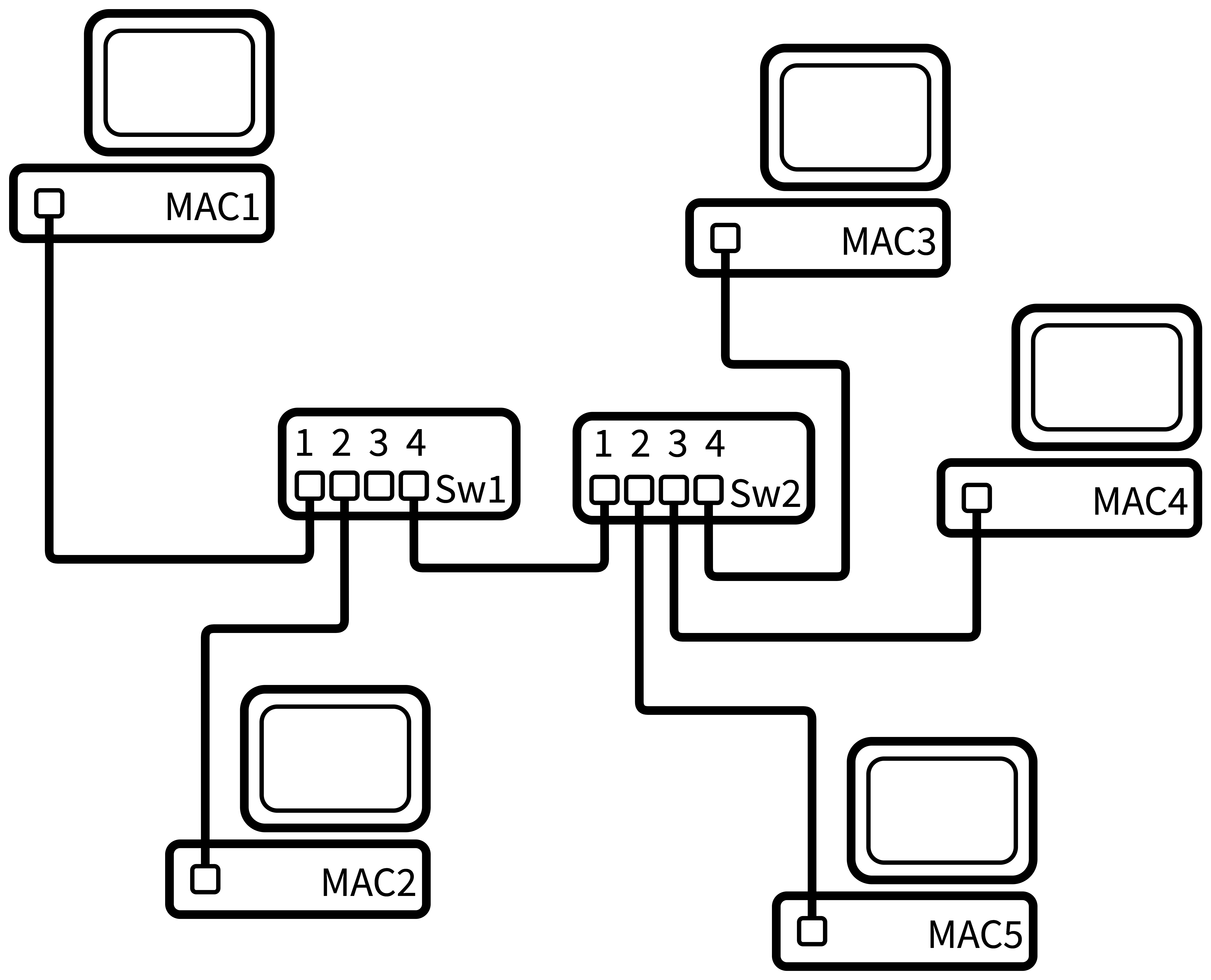
This will become clearer, hopefully, with an example. In all the examples that follow, I’ve shortened device MAC addresses from 70:3a:cb:8d:5a:e9 to more easily recognisable things, like MAC1 for the MAC address of device 1. Things like switches and access points don’t strictly need MAC addresses, but often do, so you can access configuration servers that they run. Without those, it’d be impossible to route frames to the servers because they wouldn’t have an address to send your data to. Anyway, on with the example.
| MAC address | Forwarding Port |
|---|---|
| MAC1 | 1 |
| MAC2 | 2 |
| MAC3 | 4 |
| MAC4 | 4 |
| MAC5 | 4 |
As MAC3, MAC4 and MAC5 are connected to Sw2, for Sw1 they all appear to be reachable over port 4.
Switch 2 will create this MAC address table:
| MAC address | Forwarding Port |
|---|---|
| MAC1 | 1 |
| MAC2 | 1 |
| MAC3 | 4 |
| MAC4 | 3 |
| MAC5 | 2 |
If MAC1 wants to send data to MAC5:
- MAC1 creates an ethernet frame with
(source:MAC1, destination:MAC5). - MAC1 sends its frame out of its ethernet port, and it reaches Switch1.
- Switch1 receives the frame over port 1. It reads the destination of MAC5, and sees that it has an entry, so forwards the frame on port 4.
- Switch2 receives the frame over port 1. It reads the destination of MAC5, and sees that it has an entry, so forwards the frame on port 2.
- MAC5 receives the frame, sees that it is the intended recipient, and decodes the frame to receive the data.
Each switch doesn’t know whether the device with that MAC address is directly connected to it or not. All it knows is that given devices are reachable over given ethernet ports. Commonly, switches are connected to other switches, meaning that a given physical port on a given switch may see frames from many different source MAC addresses. In this case, the switch will have may MAC addresses associated with the same outgoing port in its MAC address table. This is fine, as each of those addresses should be reachable from that port. The destination switch will figure out where to go from there. This is why the switch only cares about how to get to the next hop: the port over which it needs to forward the frame to (hopefully, eventually) get it to its destination.
Over time, devices may be switched off, new devices appear, and existing devices may be cabled into a different switch. This means that the internal MAC address table can get out of date, in which case the switch will forward frames to the wrong place. To account for this, each MAC address table entry has a time to live, after which it’s removed from the table. This limits the duration of the network breakage.
In addition, switches can be physically wired together such that they form loops. In this case, the Spanning Tree Protocol is used by the switches to work out a single, non-looping route for each MAC address on the network.
Once I’d learned all this, I felt confident in how wired networks get data around, and the basics of how layer two was going to work. Now I needed to add wifi to my picture, and so I first looked at wifi frames.
I learned a bunch of this from this computer networking book.
Wifi Frames
Both layer 1 (PHY, the physical transmission of bits) and layer 2 (MAC/frame layer) are defined in the series of 802.11 standards.
It’s interesting to talk a bit about how layer one in wifi works. It didn’t help that much in the question of whether the network would function, but it did help me understand/guess whether I was going to end up with something that performed terribly (I didn’t).
At layer one, the physical layer, wifi uses the amplitude and phase of an electromagnetic (radio) wave to transmit bits in the air. In general, to stop each devices waves getting muddled with other devices, at a given moment in time only a single device can transmit or receive data to an access point. This means that devices take turns speaking to their access point. It’s all very polite. This is similar to ethernet, where only one device can be active on the wire at a time.
Wifi access points (APs) select a frequency space (2.4Ghz, 5Ghz) and a channel within that frequency, and use that to communicate with their clients. All clients and access points that share a channel must take turns transmitting and receiving. That’s why it’s wise to choose a different channel to your neighbours, as otherwise both your devices and their devices must all take turns with each other. If you both use your own channel, at least it’ll only be your own devices taking turns. (This is all enforced solely by the Wifi Alliance only giving wifi stickers to devices that do this right rather than by some magic technology).
Wifi frames, like ethernet frames, are preceded by a preamble, which allows a receiver to notice that there is a wifi frame about to appear out of the air. Following that preamble is the frame itself. Unlike ethernet, there are a whole host of different frame types that wifi defines:
- Frames that APs broadcast to advertise their networks (identified by basic service set IDs or BSSIDs; the MAC address of an AP).
- Frames used during the protocol a client uses when associating itself with an AP (ie, joining a wireless network).
- A frame to ask an AP if you can send data to it now.
- Several frame types that are to do with carrying payload data.
As with ethernet frames, along with other metadata, the wifi frame header carries details of the source and destination MAC addresses. However, it doesn’t just carry these: there are up to four address fields in the header!
There are four addresses because there are four roles within the wifi environment, each potentially having their own MAC address:
- The ultimate source of the frame (eg, a laptop).
- The ultimate destination of the frame (eg, a speaker).
- The transmitter of the frame (the device with an aerial that sends data).
- The intended receiver of the frame (the device with an aerial that receives data).
Having these four roles is more understandable when you realise that both the source and destination devices may not be wifi devices themselves, but instead devices connected via ethernet to a wifi access point. In most scenarios, however, more than one of these roles may be performed by the same device. If they are, fewer addresses are included in the frame.
- Two addresses can be used where the source is the transmitter, and the destination is the receiver. This is used in ad-hoc wifi networks. This is where two devices, such as laptops, connect directly to each other over wifi and send data between themselves.
- Three addresses are used in the frames between a wireless access point and its clients. We’ll look at that next.
- Four addresses are used in WDS, used for bridging two ethernet networks using wifi, which we’ll get to after that.
Wifi access points
The common case today is where a wifi access point is used. Two devices are communicating with each other. One device and the access point itself are connected to the same wired network. The second device is connected wirelessly to the access point; it is an associated wireless client of that access point. Data that needs to go between the two devices must go via the access point.
Wifi networks were designed to be added into existing ethernet networks. A key way this happens is that wifi client MAC addresses have the same format as wired MAC addresses – so you can embed a wifi client MAC address into a standard ethernet frame, and send it on its way through the network.
To understand how this works, let’s take a similar network to the one we used above but connect MAC5 to a wifi access point:
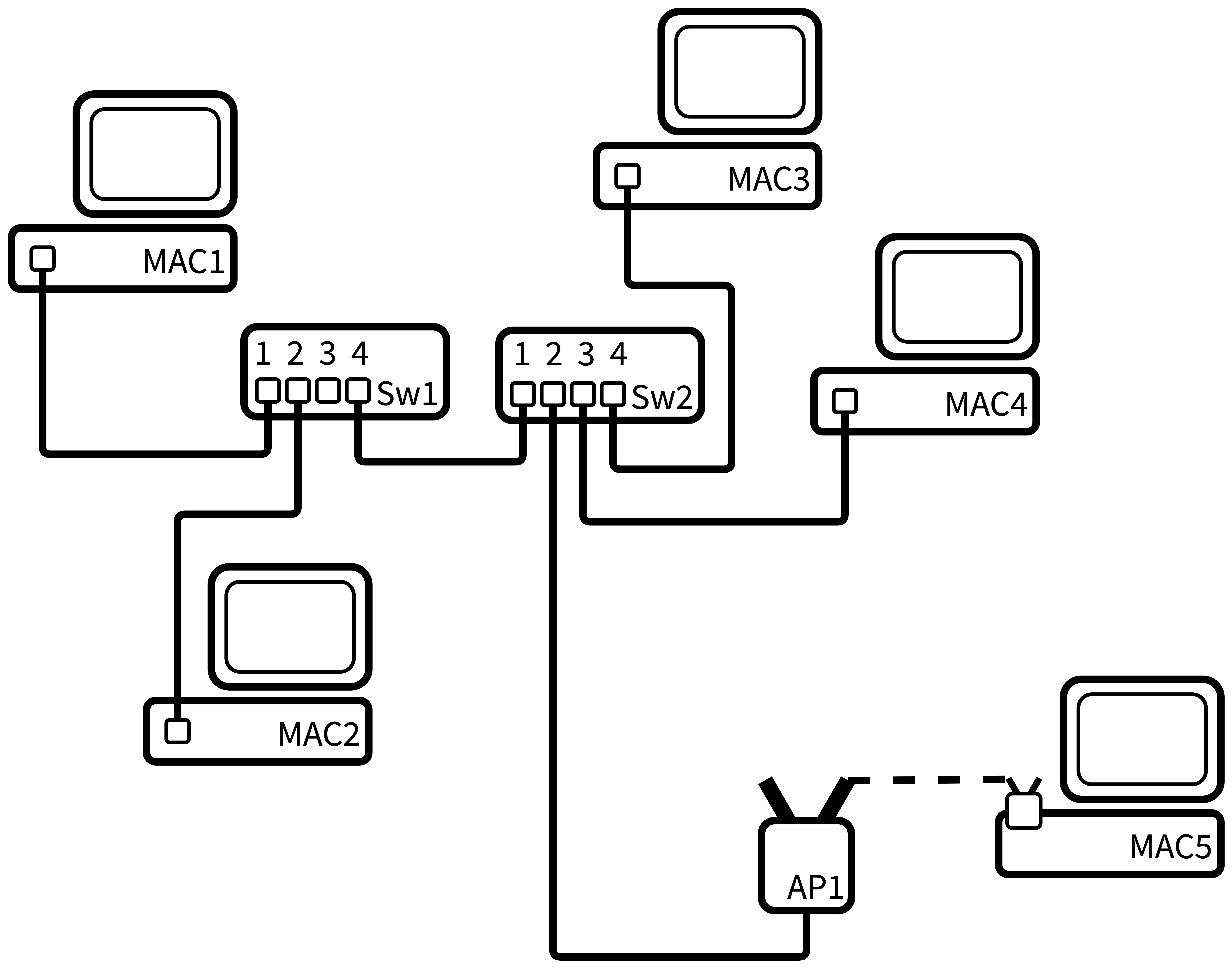
Again, let’s look at how MAC1 sends a frame to MAC5. The switches will go about creating their MAC address tables as usual. They will see MAC1 and MAC2 as source addresses and add them. But they will also see MAC5 just the same – the access point will create ethernet frames from the wifi frames it receives from MAC5, and as the wifi MAC address for MAC5 is just the same as an ethernet MAC address in terms of format, the switches can add wifi client MAC addresses as usual when they see MAC5’s address in the source field of a frame. To the switches, therefore, the wifi access point is transparent.
So, in this network, because to the switches the wireless MAC address of MAC5 looks just like an ethernet MAC address, Switch 1 (Sw1) can again create the following mapping table:
| MAC address | Forwarding Port |
|---|---|
| MAC1 | 1 |
| MAC2 | 2 |
| MAC3 | 4 |
| MAC4 | 4 |
| MAC5 | 4 |
Switch 2 will again create this one:
| MAC address | Forwarding Port |
|---|---|
| MAC1 | 1 |
| MAC2 | 1 |
| MAC3 | 4 |
| MAC4 | 3 |
| MAC5 | 2 |
Just what do access points know?
At this point, I wondered: what does an access point need to maintain? What’s its equivalent of a switch’s MAC address table? Unlike the myriad of descriptions of switches building up MAC address tables, I couldn’t really find details online (I’m sure it’s there, even if its deep inside the 802.11 spec somewhere). So, to some theorising. After reading a whole bunch and then some more, I thought about each frame it could receive over its two interfaces (the wireless and wired ones) and what it’d do with them:
- A frame over either wired or wireless with a destination MAC address that is one of its wireless clients. It can forward that frame to the wireless client.
- A frame over wireless with a destination MAC address that is not one of its wireless clients: the AP can assume that the frame is destined for someone on the wired network and just forward it onto that network.
- A frame over wired with a destination MAC address that is not one of its clients: there’s no point sending the frame back over the wired connection, and it’s not for the AP’s wireless clients, so the AP can discard the frame.
From this, the only thing that an AP appears to need is a table of its associated clients. I’m sure that an AP could maintain other tables, but the list of its clients seems the only essential one for routing.
Being clear that this is essentially my guess as to what’s going on, I assume that AP1 has the only the list of associated client MAC addresses:
| Client ID | MAC Address |
|---|---|
| 1 | MAC5 |
So, now if MAC1 wants to send data to MAC5:
- MAC1 creates an ethernet frame with
(source:MAC1, destination:MAC5). - MAC1 sends its frame out of its ethernet port, and it reaches Switch1.
- Switch1 receives the frame over port 1. It reads the destination of MAC5, and sees that it has an entry, so forwards the frame on port 4.
- Switch2 receives the frame over port 1. It reads the destination of MAC5, and sees that it has an entry, so forwards the frame on port 2.
- AP1 receives the frame over its ethernet port (from the “distribution system”) and decodes it. It sees that MAC5 is an associated wireless client, so wraps the frame’s payload in an 802.11 frame and broadcasts it over the air. The 802.11 frame will have
(source:MAC1, destination/receiver:MAC5, transmitter:AP1) - MAC5 sees and receives the frame from the air, sees that it is the intended recipient, and decodes the frame to receive the data.
Wifi frame address fields
Between MAC1, MAC5 and AP1 there are three participants in the exchange, so wifi frames passing between AP1 and MAC5 use three of the four addresses.
When MAC1 is sending data to MAC5, the wifi frame is transmitted by the access point and received by MAC5. The addresses are set as follows:
- Address 1: MAC5 address (both destination address and receiver address in 802.11 terms, the laptop wifi adapter’s MAC address)
- Address 2: AP1 address (transmitter address in 802.11, this is the AP’s BSSID)
- Address 3: MAC1 address (source address in 802.11)
- Address 4: unused
- (802.11 frames call this
ToDS=0,FromDS=1)
When the wireless MAC5 is sending to the wired MAC1, the wifi frame is transmitted by the MAC5 and received by the access point. The addresses are set like this:
- Address 1: AP1 address (receiver address in 802.11, the AP’s BSSID)
- Address 2: MAC5 address (both transmitter and source address in 802.11)
- Address 3: MAC1 address (destination address in 802.11)
- Address 4: unused
- (802.11 frames call this
ToDS=1,FromDS=0)
The distribution system
What are those ToDS and FromDS terms? They are two 1 bit fields in the wifi frame header. In the 802.11 (wifi) standards, an access point extends a wired network into the wireless domain. The standards call the wired network the “distribution system” or DS. So, within the standard, an access point is either sending data from the distribution system to a wireless client (FromDS=1,ToDS=0, “from the distribution system: yes, to the distribution system: no, to a wireless client”), or sending data to the distribution system from the wireless client (ToDS=1,FromDS=0). The wireless frame sets the two 1-bit fields based on this.
The ToDS=1,FromDS=1 case is used when wifi is used to bridge between two wired networks, so both ends of the wifi hop are connected a distribution systems. For completeness, in the ad-hoc network case it’d be ToDS=0,FromDS=0, because both ends of the connection are end devices rather than distribution systems.
So why do we need all three addresses? I couldn’t really find any explicit details, but my reasoning is that:
- Sent from AP1 to MAC5:
- As well as the source (MAC1) and destination (MAC5), we need the transmitting AP address so the client (MAC5) can know the frame came from a router it is associated with. MAC5 can also learn that it can use AP1 when it needs to send something to MAC1.
- Sent from a MAC5 to AP1:
- As well as the source (MAC5) and destination (MAC1), the frame needs to embed the receiving AP’s address so AP1 knows the frame is destined for it.
Why do we need all that information about the AP(s) involved in the frame? In ethernet we have physical wires going into ports on the network device or computer. So we know that something coming in through that port is (by definition) something that’s on “our” network. Whereas in a wifi environment – like in a block of flats – there are potentially many different APs on many different networks that will be in the range of a wifi transmission, and the AP needs to know whether the frame it’s reading from the air is for itself or not.
Of course, it’d be trivial for a malicious actor to just read frames out of the air that were not destined for them and thereby sniff the traffic. WPA2/3 addresses this problem by establishing a secure tunnel between a device and an AP, encrypting the traffic between them such that anyone who reads the frame out of the air cannot read the data contained within it.
Aside: wireless distribution system (WDS)
We need to understand wifi mesh networks to understand my Google Wifi network. And to understand mesh, we first need to take a quick look at the part of 802.11 known as the wireless distribution system, or WDS.
The forth address in the wifi 802.11 frame format is to support this wireless distribution system thing. This is where you use a wireless connection to connect two wired networks together to form one large network. There are two ways you can use WDS:
- The first way is called a wireless bridge. The access points involved in this connection cannot have other clients connected to them, they are purely for connecting the two wired networks. For example, this could be used to connect two office buildings across the street from one another into a single network without digging up the road.
- The second is wireless repeater. In this mode, one access point is connected to the wired network and the second both connects to the first and has wireless clients. This is the typical way that’s it’s used in a house, as a way to get around wireless “dead spots”.
Unfortunately, the specification didn’t get too detailed about how a WDS should be implemented by access points beyond including the four addresses address. One key omission was how to create a secure connection between the APs. What this has meant in practice is that different manufacturers implemented things differently enough in practice that using devices from different companies is an unwise thing to attempt. There are more details in this piece.
Wireless bridge
The network would look like this:
In this network, the switches maintain the same MAC address tables as when the switches were connected directly together. Switch 1 will forward frames for MAC3, MAC4 and MAC5 over its port 4. Similarly, Switch 2 will forward frames for MAC1 and MAC2 over port 1. AP1 will forward all frames to AP2 and vice versa. In this manner, the WDS bridge is functionally transparent to the rest of the network.
In this network, frames going over the WDS connection use all four addresses. If MAC1 is sending a frame to MAC5, which needs to go over the AP1 to AP2 WDS, the addresses in the wifi frame are set like this:
- Address 1: AP2 (receiver address in 802.11).
- Address 2: AP1 (transmitter address in 802.11).
- Address 3: MAC5 (destination address in 802.11).
- Address 4: MAC1 (source address in 802.11).
As well as the source (MAC1) and destination (MAC5), the frame includes the receiving AP’s address (AP2) so AP2 knows the frame is destined for it. It also includes the transmitter’s address which allows AP2 to know the frame is coming over the WDS it has set up with AP1. Potentially AP2 can infer that it can use AP1 to route frames to the source (MAC1) through AP1, which would allow it to drop frames rather than send everything over the WDS link.
Wireless extender
A wireless extender has a WDS link to a wired AP and shares that link with wireless clients. The link is shared over a new wireless network. That new wireless network might be given the same name (SSID) and security settings (eg, password) as the original network, which means that devices can connect to it relatively transparently. Alternatively, it can have a new SSID, meaning a user has more visibility on when the extender network is being used.
Wireless extenders have a bad rap, mostly deservedly. It’s wise to use devices from the same manufacturer; this usage is more complex and, accordingly, has a worse history of interoperability. Throughput is often pretty bad – the connection between the client device and the extender AP must take turns with the extender AP to wired AP connection, which halves the available bandwidth and increases latency substantially. Throughput can be improved using techniques such as dedicating the 5GHz band to the AP to AP connection, and using only 2.4Ghz for clients.
Mesh wifi
Mesh wifi appears to be mostly defined by the fact that you buy several pieces of kit that are designed to work together to form a reliable set of client access points joined together by wifi rather than wires (though most also support wiring the devices together). It’s not clear whether early mesh network products were just WDS extenders, along with some proprietary configuration magic.
Effectively, my Google Wifi access points assume they’ll be set up in a mesh-style topology. They are built to be easily configured that way in home environments where there isn’t a network expert handy. That seems to be the main thing about them being “mesh”.
While mesh kit started to appear quite some years ago, they were fully proprietary. After a while, the concept got a standard in the 802.11s specification. The specification tries to create a common definition of terms and understanding about questions like:
- How do mesh APs discover each other?
- How to they set up secure channels?
- How do they prevent unauthorised APs joining the mesh?
- How should packets be routed in mesh networks with loops?
That specification is used in some mesh networking kit, including my Google Wifi APs. One thing that 802.11s defined is how devices using wireless backhaul links could connect securely – as noted, WDS left this undefined which was one of the reasons implementations didn’t interoperate. However, even though 802.11s exists, I’d personally not be terribly confident in using different manufacturer’s devices, as the specification appears to (intentionally) leave space for proprietary implementation and extension.
I found that this document at the Certified Wireless Network Professionals (CWNP) site was a very good introduction to the details. The CWNP site has some other good whitepapers on wireless network standards.
The mesh specification defines how two or more APs to connect to each other over a wireless backhaul to create a network. Like a WDS extender, each AP may also have its own wireless clients. Some AP models use a separate channel for the backhaul to the client network, but most consumer mesh wifi (such as my own Google Wifi) shares the channel between clients and the backhaul. As this means that backhaul and clients share the link and must take turns, this is not quite as efficient as a dedicated backhaul link. But it works fast enough for home users.
In my Google Wifi mesh network, all devices connected to the mesh appear to be on the same LAN. I’m not sure if this is true for all mesh networks.
Let’s take a look at routing in this network, which has a mesh between three APs alongside a small wired network:
Note that AP2 and AP3 are not able to connect to each other, instead they are only connected to AP1. The specification allows the loops that would form if AP2 and AP3 were also connected, and defines behaviour in that scenario. But for now I’m ignoring it.
As we’ve seen previously, the wireless network is transparent to the wired network. Therefore Switch 1 (Sw1) will yet again create the following mapping table:
| MAC address | Forwarding Port |
|---|---|
| MAC1 | 1 |
| MAC2 | 2 |
| MAC3 | 4 |
| MAC4 | 4 |
| MAC5 | 4 |
Mesh network access point MAC address tables
Now we are dealing with a mesh network, being again clear this is my guesswork, my reckoning is that AP1 now needs two tables.
First, as before, is its list of connected clients:
| Client ID | MAC Address |
|---|---|
| 1 | MAC3 |
The second is a bit more like a switch’s MAC address table. A mesh network may have multiple wireless hops between the source and destination, so an AP needs to create a MAC address table that maps from MAC addresses to the next hop access point. So AP1 would end up with:
| MAC address | Forwarding AP |
|---|---|
| MAC4 | AP2 |
| MAC5 | AP3 |
For any other destination MAC address, just like a non-mesh AP, AP1 can forward the data onto the wired network.
AP2 and AP3 both need to similarly maintain a list of their connected clients alongside the second MAC address table of next hop APs. AP2’s client table would contain MAC5, but its MAC address table ends up with entries for all the other devices on the network, as a switch’s might:
| MAC address | Forwarding AP |
|---|---|
| MAC1 | AP1 |
| MAC2 | AP1 |
| MAC3 | AP1 |
| MAC5 | AP1 |
Of course, in this network the wireless clients can move around. In the same way as a wired client may be cabled into another switch, over time MAC4 may move to AP1, and MAC address tables will change as that happens.
A wrinkle: Google Wifi mesh access points have LAN ports 🤯
So far, we’ve spoken about access points as if they can only ever have a single wired connection, the one that goes to the wired network or the distribution system. These are what one might call “pure” access points. However, right at the start of the article, I discussed how my Google Wifi routers have both a WAN port and a LAN port. It appears that they connect to two distribution systems! That doesn’t gel with what I’d learned so far.
I couldn’t find anything about special-casing devices with two ethernet ports. So I decided I just needed to view Google Wifi devices as box containing multiple logical (ie, software) devices: a switch, a router and an AP. The WAN port connects to the router. The router connects to a switch which also connects to the LAN ethernet port and the wifi AP. As we saw above, the switch can just learn its MAC address table as usual, receiving from and forwarding to the router, LAN or AP as appropriate. At least one random site on the internet agreed with me, calling this a “multifunction access point”.
Only one of the Google Wifi devices in a mesh has its router functionality enabled. A router connects different IP networks together at layer 3, so the “router” Google Wifi device is the one that has its WAN port connected to the upstream network; here, that’s my ISP.
Google Wifi automatically disables the router function of the other APs in the mesh and sets them up as layer 2 network bridges. As a network bridge creates a single network from multiple network segments (in this case the wireless and ethernet clients of each AP), this is also why all devices connected to all the Google Wifi APs in the mesh appear to be on a single LAN. This is important for Sonos speaker auto-discovery magic which uses broadcast packets via SSDP (albeit AirPlay uses Bonjour/Zeroconf); see Operating Sonos Speakers in a Multi-VLAN Network for why the single network makes things much easier.
For now I’m going to ignore the fact one Google Wifi AP is also a router. This is because I don’t think that it impacts our layer 2 routing. I’ll just assume that if a device is sending an IP packet to the outside world, it knows the router Google Wifi device is the gateway that it should send the packet to. And vice versa, on receiving a packet from outside, the router can work out the destination’s MAC address (using NAT to get a private address/port, then ARP to get the MAC address) and encapsulate the IP packet into an appropriate frame.
Finally figuring out whether I could have an AP in the study
Goodness, it’s taken a while to get here. But now I kinda mostly sorta understand what’s going on with the devices on the network, at least to the extent that I can reason whether the setup I want to use will work. My desired setup looked like this:
We have one router, three switches, three access points, two laptops and one speaker. (It’s simplified of course: phones, iPads, watches, Kindles, smart bulbs, FireTVs and other speakers not shown 🙃).
I used an old Airport Express in the study in the garden, because I didn’t want any smarts in a Google Wifi point to get in the way (eg, try to join the mesh). I set up that AP with a new wireless network. I also had to make sure to also set up the Airport Express in network bridge mode, to ensure the device’s associated with the AP appeared on the same network as all my other devices.
Looking at what I’ve learned, the key thing that stands out to me is that wifi was designed to fit into ethernet networks. As I’ve gone through each of the setups through from the ethernet switches to the wifi mesh network, each device has been building up MAC address tables that look remarkably similar from the older technology all the way through to the newer mesh technology.
Let’s simulate a network in our heads 🧙♂️
I found the easiest way to prove to myself this network would work was to think through the MAC address tables at each device.
To do this, I assumed that each laptop and the speaker would send out a broadcast frame when it came online – say during DHCP – and that the layer two devices on the network would flood the network with that packet (flooding is where a switch or access point forwards over all its interfaces – so, for example, all the ethernet ports for a switch). I could then follow a frame to see if each device would see it, and so add the sending device to its MAC address table.
Let’s first use Laptop 1 as our example:
- Laptop1 sends a broadcast frame over wifi to AP2
- AP2 forwards to AP1 and Sw2.
- AP1 forwards to Sw1.
- Sw2 forwards to Sw3.
- Sw3 forwards to AP3.
- AP2 forwards to AP1 and Sw2.
And, from the other end of the network, Spk1 (this same thing would happen for Laptop2):
- Spk1 sends a broadcast frame over wifi to AP3.
- AP3 forwards to Sw3
- Sw3 forwards to Sw2.
- Sw2 forwards to AP2.
- AP2 forwards to AP1.
- AP1 forwards to Sw1.
- AP2 forwards to AP1.
- Sw2 forwards to AP2.
- Sw3 forwards to Sw2.
- AP3 forwards to Sw3
We can see that both devices have their frame ending up at all the layer two network hardware! This is great news! It means that every layer two device will be able to add an entry to its MAC address table with a next hop for both laptops and the speaker.
Let’s take the Google Wifi device with Sw2 and AP2 sat inside it as our example.
I built Sw2’s MAC address table to look like this:
| MAC address | Forwarding Port |
|---|---|
| LAPTOP1 | 1 |
| SPK1 | 4 |
| LAPTOP2 | 4 |
| ROUTER | 1 |
AP2 would have the two mesh wifi tables:
First, its list of associated, connected clients:
| Client ID | MAC Address |
|---|---|
| 1 | LAPTOP1 |
Second, its mesh MAC address table thing:
| MAC address | Forwarding AP |
|---|---|
| ROUTER | AP1 |
And AP2 would assume any packets destined for LAPTOP2 and SPK1 could be sent through the distribution system, ie, using its “local” switch, Sw2.
A bit more work made it clear that each of the other access points and switches could also build correct tables. I’ll not draw them all out here.
The moment it came alive
By this point I was quietly confident that it should all work just fine. I was happy that frames should be routable between devices on all the various bits of network and, because of the network bridge mode in the APs, I was confident that the speaker auto-discovery would work too. But I wouldn’t have been at all surprised if it hadn’t worked – I worried there was some key thing I was assuming that just wasn’t true, even after all my research. After all, my access point device tables were essentially guessed at, and I’d glossed over a bunch of things, such as whether I should care about the Spanning Tree Protocol.
But thankfully, after connecting the study Airport Express to the ethernet cable, turning it on and setting it up, everything worked. The laptop can work both wired and wirelessly connected to the Airport Express. The speakers work fine, albeit with a few bits of confusion in the Sonos application (which assumes, quite reasonably, that you won’t have two wireless network SSIDs on the same LAN).
I’m pretty happy with this set up. I’d forgotten a bunch about ethernet since university so had to relearn the details of that. Then I had to augment that knowledge with a bunch of stuff about Wifi. But it feels good to be confident about what’s going on in the network. It allows me to be happy that it’s not all working just by lucky accident. Without this, I’d be fearful of making changes.
So was I right to be worried that this wouldn’t work?
In the end, by using the Google Wifi points to create the wireless backhaul to the ethernet cable out to the study, and connecting a relatively bog-standard AP to the other end of the cable, everything functioned without much effort at all on my part; frankly it would’ve worked just fine if I’d not read a zillion things on the internet first and instead just tried it. However, I am glad I did the reading because now I am confident in its working and not worried about altering the setup.
But I think that if I’d tried doing this without the mesh wifi already in place – that is, buying another off-the-shelf WDS extender of some kind – then I’d have had a bit more work to configure it correctly and have it work with whatever existing router that I had, ensure it was in bridge mode and so on. Probably I’d have needed to match the manufacturer if I wanted any support with the WDS bridge (eg, this netgear page states “Technical Support does not provide free help setting up WDS between NETGEAR access points and non-NETGEAR equipment.”). That the Google Wifi mesh set up automated all this configuration was a big thing in enabling this setup to work easily for me.
Overall, I’d say that I came away from this experience feeling that spending too much time learning about networking in too much detail was, in fact, a good way to have too much fun for too many evenings 😂